Resurrecting 1970 GM AC with POA
Posted: Mon Aug 20, 2018 4:08 pm
Hi my name is Clint and I'm working to get the factory air working on my 1970 Chevrolet Nova. I am a mechanical engineer with a background on the theory of refrigeration cycles, but this is my first time diving into the practical implementation of automotive AC. I stumbled on this forum while researching POA valves a few years ago and I hope sharing my experience here will establish two-way learning. Thank you for any help/advice you can offer as I work through this!
The Car and System
My car is a factory AC 1970 Nova. I have swapped the engine for a modern LS engine, but I've kept the factory AC "suitcase" on the firewall, retaining the evaporator and all the factory controls. Here is what the car looks like inside and out:


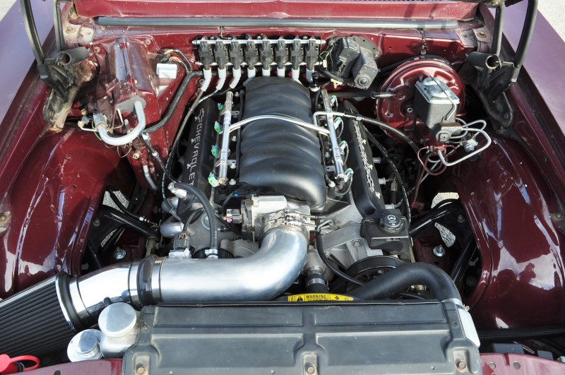
The original system uses a thermostatic expansion valve (TXV) and pilot operated absolute suction throttling valve (POA STV). I plan to keep these components and the original evaporator and controls, but I will be connecting them to fresh barrier hoses, a modern parallel-flow condenser, new drier, and a Denso 10S17 compressor which I've tucked down low in the OEM location on the LS engine. I will also be converting to R134a. The system uses a two-speed electric fan for radiator and condenser airflow.
Theory of Operation
The operation of the system will, as originally designed, run the blower and compressor full time any time the AC or defroster is selected. The original HVAC controls have mechanical/cable duct controls to route air through the evaporator and/or heater core depending on whether the system is in AC, blend or defrost mode and incorporates a vacuum valve to open and close fresh or recirculated air. It also had a vacuum-controlled valve to shut off flow to the heater core when in AC mode.
The refrigeration cycle basically works as follows:
1 - Vapor refrigerant at low pressure is compressed to a high pressure by the compressor which leads to an increase in temperature above ambient.
2 - Vapor refrigerant at high temperature and high pressure then delivered to the condenser in front of the car where ambient air blowing across the condenser removes energy from the refrigerant and it condenses into a liquid. This heat transfer is possible because the refrigerant is at a higher temperature than ambient.
3 - High pressure liquid refrigerant passes through a drier which traps any moisture and prevents it from circulating in the system.
4 - High pressure liquid refrigerant passes through a small restriction at the TXV which causes the liquid to drop to a low pressure and low temperature (see more explanation on the TXV valve below)
5 - Low pressure low temperature liquid refrigerant evaporates inside of the evaporator by sucking heat from the air passing across the evaporator into the cabin. This heat transfer is possible because the temperature of the refrigerant is lower than the ambient air passing through the evaporator into the cabin.
6. Low pressure refrigerant passes through the POA valve and back to the compressor. Under some conditions the POA valve restricts the refrigerant to maintain a minimum temperature in the evaporator (see more explanation on the POA valve below).
When the system is being used for defrost, the goal for the evaporator is to condense water out of the cabin air so dry air can be heated by the heater core and directed at the window to defrost.
The TXV valve is located at the inlet of the evaporator. It is a flow regulating device which meters the amount of refrigerant delivered to the evaporator based on superheat. It also creates the pressure drop that causes the refrigerant to evaporate. I spoke with 4 Seasons about their replacement TXV valve pn 38622 for this application and found it is calibrated to maintain a superheat of 10.5F for R134a. The TXV operates based on a reference pressure from the evaporator and an exit temperature measured by a bulb. The evaporator pressure sets the evaporation point aka saturation temperature of the refrigerant. The superheat is the difference between the saturation temperature and the exit temperature of the evaporator = essentially it's how much beyond boiled you make the refrigerant to ensure no liquid refrigerant makes it back to the compresser.
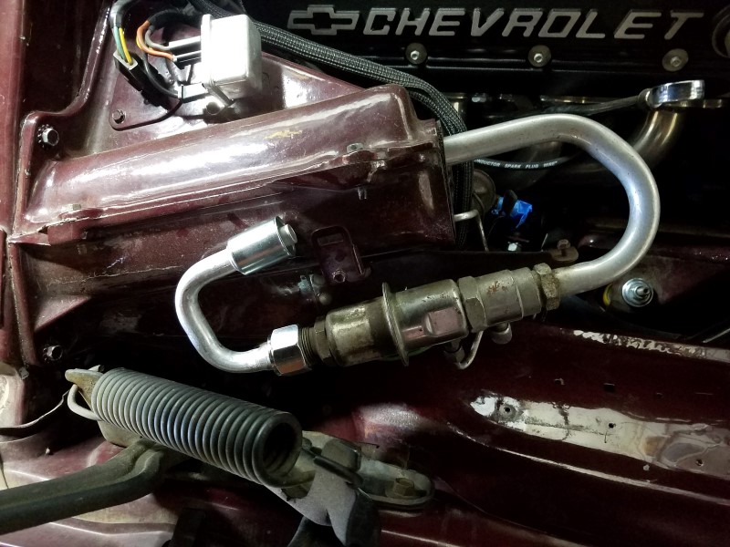
The POA valve is located at the exit of the evaporator. It is a pressure regulating device which ensures the evaporator pressure is always above a minimum setpoint. Since the evaporator pressure sets the evaporation point aka saturation temperature of the refrigerant, regulating the minimum evaporation pressure also regulates the minimum evaporator temperature. The POA is calibrated from the factory at about 30psig. For R12 freon this corresponds to a saturation temperature of 32F - the freezing point of water. By keeping the evaporator at or above the freezing point of water, the POA ensures any condensate from the cabin air does not freeze on the outside of the evaporator. This is especially important at low ambient temperatures or low blower speeds where the system is able to outpace demand and might otherwise just ice up the evaporator. Unfortunately 30psig corresponds to a saturation temperature of about 34.6F for R134a so if the POA is not adjusted, the evaporator will not perform as well. To get to 32F saturation temperature for R134a, the POA would need to be adjusted to 27.75psig.
The Plan
Compressor Electrical:
I plan to use the original system to power the AC compressor full time when the AC is running, however I will add a binary cutoff switch for over pressure / under charge cutoff at the drier.
Fan Electrical:
I will add a relay to ensure the engine fan is running any time the compressor is powered. Some people use a trinary switch for this function, but after looking at a number of trinary switches it does not appear they would run the fan at normal operating pressures. My fan will either be commanded hi/low speed by the LS engine controller OR overriden to high speed by a relay when the AC compressor is running.
Duct controls:
I have lubricated all the cables that operate the doors and flaps which direct air through either the heat core (heating/blend), evaporator (AC/blend) or both (defrost mode). There is also a vacuum valve that controls fresh or recirculated air by operating doors at the cowl and in the kick panel areas. I have not yet tested this valve or the flaps, but I will need to hook it up and make sure it and all the flaps are working properly
Heater control:
The original system uses a vacuum-controlled valve to shut off coolant flow to the heater core when the system is in AC or vent mode. However this was just a simple shutoff valve. The LS engine waterpump relies on full time flow from it's heater ports, so I will have to find a new directional control valve that will either direct coolant through the heater core or recirculate it back to the water pump.
Blower control:
The original system uses a set of resisters to achieve 3 blower speeds (low/med/high). I tested these and they are functioning properly. The system also uses a dedicated relay for the high current demand of high speed only. This relay had malfunctioned, so I replaced it and confirmed high speed now works. The blower itself is original and seems to be functioning okay. I wish there were a way to test how much air flow it's putting out - I am not sure if it's blowing as hard as it should. It certainly doesn't blow as hard as any of my modern cars, but I don't know if it's just normal for a system designed 50 years ago or if the performance has degraded over that time. Any suggestions on how to test the blower performance?
Ducting:
I have repaired a few holes in the fiberglass on the evaporator suitcase. I will look for and repair leak paths in the ducting to be sure all the air from the blower is directed where it needs to go.
Condenser/Drier
I have installed a large aftermarket parallel flow condenser tightly in front of the radiator and a new drier located in the factory location on top of the fenderwell. This should improve capacity to compensate for potential performance loss due to converting from R12 to R134a. It is a better heat exchanger than the original tube & fin design and much larger.
Compressor:
I am using a Denso 10S17 because it is the factory compressor attached to this LS engine and therefore has a good mounting and tensioner setup. I am hopeful it will provide adequate performance for this system. I am using a set of Docs Blocks adapters to go from the ports on the compressor to SAE o-ring fittings.
Hoses and o-rings:
I will fabricate custom barrier hoses using beadlock hose fittings. I will borrow a Mastercool tool to crimp the ends onto barrier hose. All the fittings will use new o-rings, including at the POA valve.
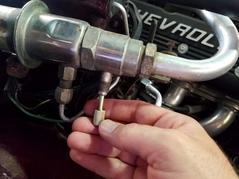
POA valve:
I will test and recalibrate the POA valve to run at a suitable pressure for R134a. As noted above if I want the saturation temperature to be 32F, the POA should be adjusted to 27.75psig, however I have seen people on here adjusting it to lower pressures for example 26psig which corresponds to a saturation temp of about 30F (a couple degrees below freezing). I do not want the evaporator to ice up if I use this for defrost or at low blower speeds - does anyone have suggestions on where to set the POA valve?
TXV valve:
I will replace my valve with a new one from 4 Seasons pn 38622 which is calibrated for R134a
Flushing:
I will flush out the POA valve and the evaporator using an over-the-counter aerosol flush. Since the POA valve is easily removed I will bench flush it and coat the inside with oil (fill and dump out) so make sure it has lubrication at startup. I will have to flush the evaporator on the car, so my plan is to spray flush into the upper outlet fitting and attach a clear hose to the inlet so I can direct the flush into a bucket. I will then have to blow out the evaporator with compressed air from the outlet side because it will otherwise trap flush in the bottom.
Charging:
A friend of mine does refrigeration work and will help me with charging the system, however I am not sure what method should be used to establish the right amount of R134a for this hybrid system. All the volumes in the system will be different from original due to a larger condensor and different hose routings, so I don't know if the original R12 charge amount would be a good starting point. I may have to charge using the sight glass and/or approximate pressures. If anyone has a link or can suggest an appropriate method for charging please let me know!
Oil:
I could use suggestions on what oil and how much to use. I was thinking about using Ester100 because of dual compatibility, but the Denso compressor was originally used with PAG46. I am also not sure how much oil or refrigerant to use since I have created a hybrid system
Thank you for any help/support as I embark on this journey! I will begin sharing photos and video soon detailing the process.
The Car and System
My car is a factory AC 1970 Nova. I have swapped the engine for a modern LS engine, but I've kept the factory AC "suitcase" on the firewall, retaining the evaporator and all the factory controls. Here is what the car looks like inside and out:
The original system uses a thermostatic expansion valve (TXV) and pilot operated absolute suction throttling valve (POA STV). I plan to keep these components and the original evaporator and controls, but I will be connecting them to fresh barrier hoses, a modern parallel-flow condenser, new drier, and a Denso 10S17 compressor which I've tucked down low in the OEM location on the LS engine. I will also be converting to R134a. The system uses a two-speed electric fan for radiator and condenser airflow.
Theory of Operation
The operation of the system will, as originally designed, run the blower and compressor full time any time the AC or defroster is selected. The original HVAC controls have mechanical/cable duct controls to route air through the evaporator and/or heater core depending on whether the system is in AC, blend or defrost mode and incorporates a vacuum valve to open and close fresh or recirculated air. It also had a vacuum-controlled valve to shut off flow to the heater core when in AC mode.
The refrigeration cycle basically works as follows:
1 - Vapor refrigerant at low pressure is compressed to a high pressure by the compressor which leads to an increase in temperature above ambient.
2 - Vapor refrigerant at high temperature and high pressure then delivered to the condenser in front of the car where ambient air blowing across the condenser removes energy from the refrigerant and it condenses into a liquid. This heat transfer is possible because the refrigerant is at a higher temperature than ambient.
3 - High pressure liquid refrigerant passes through a drier which traps any moisture and prevents it from circulating in the system.
4 - High pressure liquid refrigerant passes through a small restriction at the TXV which causes the liquid to drop to a low pressure and low temperature (see more explanation on the TXV valve below)
5 - Low pressure low temperature liquid refrigerant evaporates inside of the evaporator by sucking heat from the air passing across the evaporator into the cabin. This heat transfer is possible because the temperature of the refrigerant is lower than the ambient air passing through the evaporator into the cabin.
6. Low pressure refrigerant passes through the POA valve and back to the compressor. Under some conditions the POA valve restricts the refrigerant to maintain a minimum temperature in the evaporator (see more explanation on the POA valve below).
When the system is being used for defrost, the goal for the evaporator is to condense water out of the cabin air so dry air can be heated by the heater core and directed at the window to defrost.
The TXV valve is located at the inlet of the evaporator. It is a flow regulating device which meters the amount of refrigerant delivered to the evaporator based on superheat. It also creates the pressure drop that causes the refrigerant to evaporate. I spoke with 4 Seasons about their replacement TXV valve pn 38622 for this application and found it is calibrated to maintain a superheat of 10.5F for R134a. The TXV operates based on a reference pressure from the evaporator and an exit temperature measured by a bulb. The evaporator pressure sets the evaporation point aka saturation temperature of the refrigerant. The superheat is the difference between the saturation temperature and the exit temperature of the evaporator = essentially it's how much beyond boiled you make the refrigerant to ensure no liquid refrigerant makes it back to the compresser.
The POA valve is located at the exit of the evaporator. It is a pressure regulating device which ensures the evaporator pressure is always above a minimum setpoint. Since the evaporator pressure sets the evaporation point aka saturation temperature of the refrigerant, regulating the minimum evaporation pressure also regulates the minimum evaporator temperature. The POA is calibrated from the factory at about 30psig. For R12 freon this corresponds to a saturation temperature of 32F - the freezing point of water. By keeping the evaporator at or above the freezing point of water, the POA ensures any condensate from the cabin air does not freeze on the outside of the evaporator. This is especially important at low ambient temperatures or low blower speeds where the system is able to outpace demand and might otherwise just ice up the evaporator. Unfortunately 30psig corresponds to a saturation temperature of about 34.6F for R134a so if the POA is not adjusted, the evaporator will not perform as well. To get to 32F saturation temperature for R134a, the POA would need to be adjusted to 27.75psig.
The Plan
Compressor Electrical:
I plan to use the original system to power the AC compressor full time when the AC is running, however I will add a binary cutoff switch for over pressure / under charge cutoff at the drier.
Fan Electrical:
I will add a relay to ensure the engine fan is running any time the compressor is powered. Some people use a trinary switch for this function, but after looking at a number of trinary switches it does not appear they would run the fan at normal operating pressures. My fan will either be commanded hi/low speed by the LS engine controller OR overriden to high speed by a relay when the AC compressor is running.
Duct controls:
I have lubricated all the cables that operate the doors and flaps which direct air through either the heat core (heating/blend), evaporator (AC/blend) or both (defrost mode). There is also a vacuum valve that controls fresh or recirculated air by operating doors at the cowl and in the kick panel areas. I have not yet tested this valve or the flaps, but I will need to hook it up and make sure it and all the flaps are working properly
Heater control:
The original system uses a vacuum-controlled valve to shut off coolant flow to the heater core when the system is in AC or vent mode. However this was just a simple shutoff valve. The LS engine waterpump relies on full time flow from it's heater ports, so I will have to find a new directional control valve that will either direct coolant through the heater core or recirculate it back to the water pump.
Blower control:
The original system uses a set of resisters to achieve 3 blower speeds (low/med/high). I tested these and they are functioning properly. The system also uses a dedicated relay for the high current demand of high speed only. This relay had malfunctioned, so I replaced it and confirmed high speed now works. The blower itself is original and seems to be functioning okay. I wish there were a way to test how much air flow it's putting out - I am not sure if it's blowing as hard as it should. It certainly doesn't blow as hard as any of my modern cars, but I don't know if it's just normal for a system designed 50 years ago or if the performance has degraded over that time. Any suggestions on how to test the blower performance?
Ducting:
I have repaired a few holes in the fiberglass on the evaporator suitcase. I will look for and repair leak paths in the ducting to be sure all the air from the blower is directed where it needs to go.
Condenser/Drier
I have installed a large aftermarket parallel flow condenser tightly in front of the radiator and a new drier located in the factory location on top of the fenderwell. This should improve capacity to compensate for potential performance loss due to converting from R12 to R134a. It is a better heat exchanger than the original tube & fin design and much larger.
Compressor:
I am using a Denso 10S17 because it is the factory compressor attached to this LS engine and therefore has a good mounting and tensioner setup. I am hopeful it will provide adequate performance for this system. I am using a set of Docs Blocks adapters to go from the ports on the compressor to SAE o-ring fittings.
Hoses and o-rings:
I will fabricate custom barrier hoses using beadlock hose fittings. I will borrow a Mastercool tool to crimp the ends onto barrier hose. All the fittings will use new o-rings, including at the POA valve.
POA valve:
I will test and recalibrate the POA valve to run at a suitable pressure for R134a. As noted above if I want the saturation temperature to be 32F, the POA should be adjusted to 27.75psig, however I have seen people on here adjusting it to lower pressures for example 26psig which corresponds to a saturation temp of about 30F (a couple degrees below freezing). I do not want the evaporator to ice up if I use this for defrost or at low blower speeds - does anyone have suggestions on where to set the POA valve?
TXV valve:
I will replace my valve with a new one from 4 Seasons pn 38622 which is calibrated for R134a
Flushing:
I will flush out the POA valve and the evaporator using an over-the-counter aerosol flush. Since the POA valve is easily removed I will bench flush it and coat the inside with oil (fill and dump out) so make sure it has lubrication at startup. I will have to flush the evaporator on the car, so my plan is to spray flush into the upper outlet fitting and attach a clear hose to the inlet so I can direct the flush into a bucket. I will then have to blow out the evaporator with compressed air from the outlet side because it will otherwise trap flush in the bottom.
Charging:
A friend of mine does refrigeration work and will help me with charging the system, however I am not sure what method should be used to establish the right amount of R134a for this hybrid system. All the volumes in the system will be different from original due to a larger condensor and different hose routings, so I don't know if the original R12 charge amount would be a good starting point. I may have to charge using the sight glass and/or approximate pressures. If anyone has a link or can suggest an appropriate method for charging please let me know!
Oil:
I could use suggestions on what oil and how much to use. I was thinking about using Ester100 because of dual compatibility, but the Denso compressor was originally used with PAG46. I am also not sure how much oil or refrigerant to use since I have created a hybrid system
Thank you for any help/support as I embark on this journey! I will begin sharing photos and video soon detailing the process.